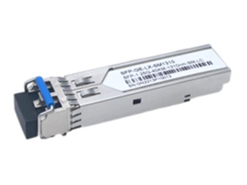
APPLICATIONS
l 25GBASE-SR Ethernet
Compliance
l SFP+ MSA.
l SFP+ SFF-8431 and SFF-8432.
l RoHS
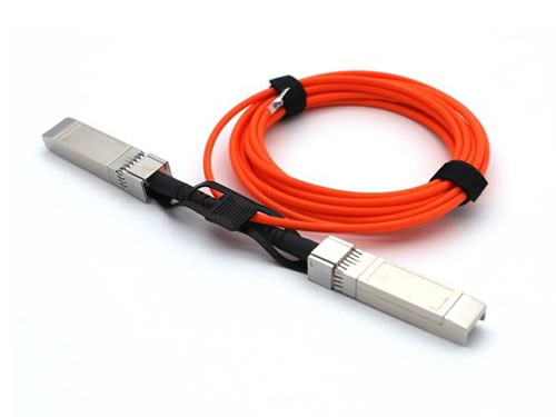
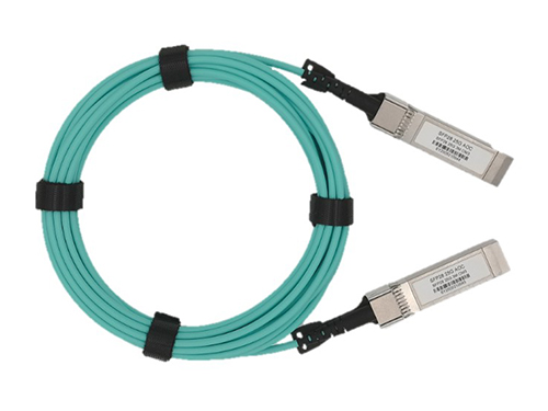
Ordering information
|
Package |
Product part NO. |
Distance |
Temperature Range |
|
SFP28 |
ESJMAA21-L05C
|
0.5-metercable |
Commercial:0~70℃ |
|
SFP28 |
ESJMAA21-M01C
|
1-metercable |
Commercial:0~70℃ |
|
SFP28 |
ESJMAA21-M03C |
3-metercable |
Commercial: 0~70℃ |
|
SFP28 |
ESJMAA21-M05C |
5-metercable |
Commercial: 0~70℃ |
|
SFP28 |
ESJMAA21-M06C |
6-metercable |
Commercial: 0~70℃ |
|
SFP28 |
ESJMAA21-M10C |
10-metercable |
Commercial: 0~70℃ |
|
SFP28 |
ESJMAA21-M15C |
15-metercable |
Commercial: 0~70℃ |
|
SFP28 |
ESJMAA21-M20C |
20-metercable |
Commercial: 0~70℃ |
|
SFP28 |
ESJMAA21-M25C |
25-metercable |
Commercial: 0~70℃ |
|
SFP28 |
ESJMAA21-M30C |
30-metercable |
Commercial: 0~70℃ |
|
SFP28 |
ESJMAA21-M50C |
50-metercable |
Commercial: 0~70℃ |
|
*For availability of additional cable lengths, please contact Esion
|
|||
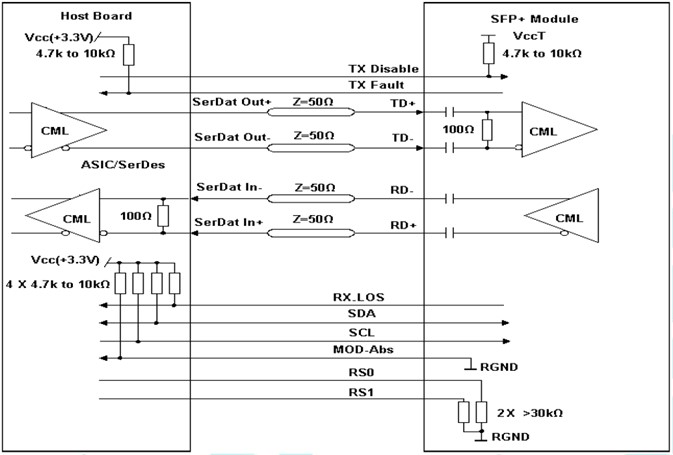
I. Pin Diagram
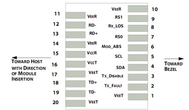
Pin out of Connector Block on Host Board
II. Pin Descriptions
|
Pin |
Symbol |
Name/Description |
Ref. |
|
1 |
VEET |
Transmitter Ground (Common with Receiver Ground) |
1 |
|
2 |
TFAULT |
Transmitter Fault. |
2 |
|
3 |
TDIS |
Transmitter Disable. Laser output disabled on high or open. |
3 |
|
4 |
SDA |
2-wire Serial Interface Data Line |
4 |
|
5 |
SCL |
2-wire Serial Interface Clock Line |
4 |
|
6 |
MOD_ABS |
Module Absent. Grounded within the module |
4 |
|
7 |
RS0 |
No connection required |
|
|
8 |
LOS |
Loss of Signal indication. Logic “0” indicates normal operation. |
5 |
|
9 |
RS1 |
No connection required |
|
|
10 |
VEER |
Receiver Ground (Common with Transmitter Ground) |
1 |
|
11 |
VEER |
Receiver Ground (Common with Transmitter Ground) |
1 |
|
12 |
RD- |
Receiver Inverted DATA out. AC Coupled |
|
|
13 |
RD+ |
Receiver Non-inverted DATA out. AC Coupled |
|
|
14 |
VEER |
Receiver Ground (Common with Transmitter Ground) |
1 |
|
15 |
VCCR |
Receiver Power Supply |
|
|
16 |
VCCT |
Transmitter Power Supply |
|
|
17 |
VEET |
Transmitter Ground (Common with Receiver Ground) |
1 |
|
18 |
TD+ |
Transmitter Non-Inverted DATA in. AC Coupled. |
|
|
19 |
TD- |
Transmitter Inverted DATA in. AC Coupled. |
|
|
20 |
VEET |
Transmitter Ground (Common with Receiver Ground) |
1 |
Notes:
1. Circuit ground is internally isolated from chassis ground.
2. TFAULT is an open collector/drain output, which is pulled up with a 4.7kΩ – 10kΩ resistor on the host board, but is grounded inside the SFP+ cable plug.
3. Laser output disabled on TDIS >2.0V or open, enabled on TDIS <0.8V.
4. Should be pulled up with 4.7kΩ – 10kΩ on host board to a voltage between 2.0V and 3.6V. MOD_ABS pulls line low to indicate module is plugged in.
5. LOS is open collector output. Should be pulled up with 4.7kΩ – 10kΩ on host board to a voltage between 2.0V and 3.6V. Logic 0 indicates normal operation; logic 1 indicates loss of signal.
III. Absolute Maximum Ratings
|
Parameter |
Symbol |
Min. |
Typ. |
Max. |
Unit |
Ref. |
|
Maximum Supply Voltage |
Vcc |
-0.5 |
|
3.6 |
V |
|
|
Storage Temperature |
TS |
-40 |
|
85 |
℃ |
1 |
|
Case Operating Temperature |
TOP |
0 |
|
70 |
℃ |
|
|
Relative Humidity |
RH |
0 |
|
85 |
% |
2 |
Notes:
1.Limited by the fiber cable jacket, not the activeends.
2.Non-condensing.
IV. Electrical Characteristics (TOP = 0 to 70C, VCC = 3.3 ± 5% Volts)
|
Parameter |
Symbol |
Min. |
Typ. |
Max. |
Unit |
Ref. |
|
Supply Voltage |
Vcc |
3.15 |
|
3.45 |
V |
|
|
Supply Current |
Icc |
|
|
300 |
mA |
|
|
Transmitter |
||||||
|
Input differential impedance |
Rin |
|
100 |
|
Ω |
1 |
|
Differential data input swing |
Vin,pp |
200 |
|
1000 |
mV |
|
|
Transmit Disable Voltage |
VD |
2 |
|
VCC |
V |
|
|
Transmit Enable Voltage |
VEN |
Vee |
|
Vee+0.8 |
V |
|
|
Receiver |
||||||
|
Differential data output swing |
Vout,pp |
200 |
|
100 |
mV |
2 |
|
LOS Fault |
VLOS_fault |
2 |
|
VccHOST |
V |
3 |
|
LOS Normal |
VLOS_norm |
Vee |
|
Vee+0.8 |
V |
3 |
|
Power Supply Noise Tolerance |
VCCT/VCCR |
Per SFF-8431 Rev 4.1 |
mVpp |
4 |
||
Notes:
1.Connected directly to TX data input pins.AC coupling from pins into laser driver IC.
2.Into 100Ω differential termination。
3.20-80%.Measured with Module Compliance Test Board and OMA test pattern. Use of four 1’s and four 0’s in sequence in the PRBS^9 is an acceptable alternative. SFF-8431 Rev 4.1
4. LOS is an open collector output. Should be pulled up with 4.7kΩ – 10kΩ on the host board. Normal operation is logic 0; loss of signal is logic 1. Maximum pull-up voltage is 5.5V.
5. Testing methodology per SFF-8431. Rev 4.1
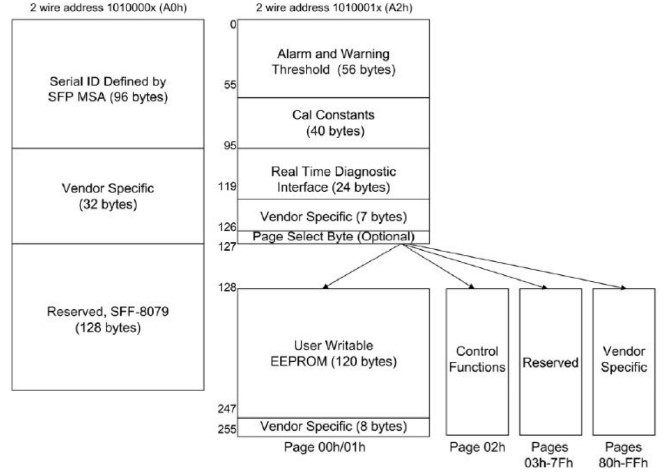
V. Digital Diagnostic Memory Map
VI. Digital Diagnostic Monitoring Information
|
Parameter |
Unit |
Accuracy |
|
Case Temperature |
℃ |
±3 |
|
Supply Voltage |
V |
±3% |
|
Tx Bias Current |
mA |
±10% |
|
Tx Optical Power |
dB |
±3 |
|
Rx Optical Power |
dB |
±3 |
VII. Recommended Interface Circuit
VIII. Mechanical Dimensions
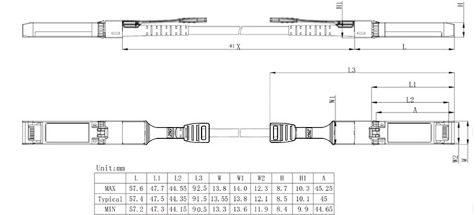
SFP wire mechanical drawing(Unit: mm)
Want to know about this product?
If you are interested in our products and want to know more details,please leave a message here,we will reply you as soon as we can.
 LPJMLB23(B32)-K40C(I)
 LPJMLB23(B32)-K10C(I)
 LPJMLM85-S10C
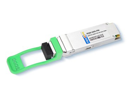
 LPJMLE31-K40C(I)
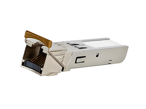
 LPJMLCxx-K10C
 LPJMLB31-K10C(I)
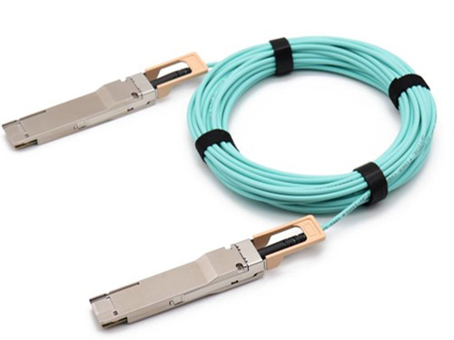
 LPJMAA31-M(L)xxC

Address : East of 2F, Tianmen Optical Valley Science Park,Qiaoxiang Economic development area,Tianmen, Hubei Province.
Tel : 15012662571
Email : chris.peng@talptech.com
Skype : 15012662571